Custom Search

Sunday, April 29, 2007

My Raptor 50

(All photos courtesy of Jo)

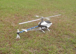
Raptor 50 with a fully bling aluminium rotor head and tail boom. My first Nitro and biggest flying heli. But it will definitely not be my last. It is used to be fitted with an Electric power plant. Due to the limited flying time with an electric setup, she now sees a brand new setup with a Nitro engine. More economical to run and longer flight duration. With a TT50 sizer, she could do 20 - 30 minutes of flight in one full tank. This is certainly a lot of flight time for me for I'm not an agressive Heli pilot. It is an awesome flying machine!


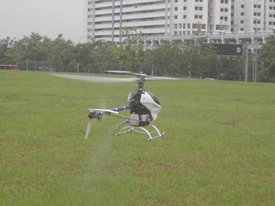
Spinning up for take off (left) & up she goes into a steady hover (right).

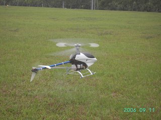
Hovering at 30cm off the ground.
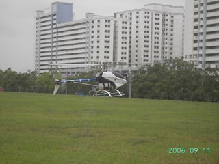
In Flight!

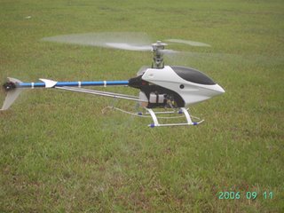
Closing in shot. Isn't she Gorgeous!

Simple Foam Cutter

A very simple to build & handy foam cutting machine good for building model airplanes.

FMS Simulator Interface

Flying Model Simulator (FMS) is a popular freeware RC Flight simulator that is easily available. However, in order to make FMS a more realistic RC Trainer, it needs to be interfaced to a transmitter.

There are instructions in the install directory of FMS on how to build a serial interface but it does require much more electronics experience. For a novice in electronics, this can take sometimes to figure out.

The other option is to buy a ready made cables off the shelf but do bear in mind they do not come cheap.

Well, here is a simple circuit that is low in cost and easy to build.

Notes: This cable is not supported by in Windows 2000 or Windows XP. However Deon van der Westhuysen has created a program called PPJOY that will allow this interface to work with Windows 2000 and Windows XP. PPJOY will also allow many various controller interfaces to work as virtual joysticks in Windows which means that the interface can be used in other games too!

Component Required
1. NPN 2222a Transistor (Many NPN transistors will work)
2. 1/2 watt 5% 10k-Ohm Resistor
3. DB25 Pin Male D-Connector
4. Shielded hood for DB25 Connector
5. 6-Pin DIN Male Plug (For FUTABA)
6. Approximately 2m of Wires
Circuit Diagram

Tx Signal and Tx GND to be connected to the appropriate Tx connector of your choice. The connection diagram for the different Tx connectors are shown below.
NPN2222 BJT DataSheet

Powered By Blogger